Building a Cross-Linked Communication Bridge with AllStarLink 3

Note: Detailed instructions and additional information can be found at the official AllStarLink documentation site.
In this post, I’ll walk you through my process of setting up AllStarLink on Debian 12, creating a private node, integrating DVSwitch, and establishing a bridge to my YSF Reflector. This setup allows seamless communication between my AllStarLink nodes and YSF-compatible devices, like my Yaesu FTM-200.
Step 1: Initial Server Setup on Debian 12
-
Update Debian Packages: Start by ensuring that your system is up-to-date.
apt update && sudo apt upgrade -y -
Install Basic Tools: It’s a good idea to install essential tools for managing your server.
apt install wget curl vim -y
Step 2: AllStarLink Package Repository Installation
To install AllStarLink on Debian 12, you need to add the AllStarLink package repository.
- Download the ASL Repository Package:
cd /tmp wget https://repo.allstarlink.org/public/asl-apt-repos_12_all.deb - Install the Repository:
dpkg -i asl-apt-repos_12_all.deb
apt update
Step 3: ASL3 Package Installation
Once the repository is added, install the ASL3 package from the AllStarLink repository:
apt install asl3
Step 4: Configuring AllStarLink Node
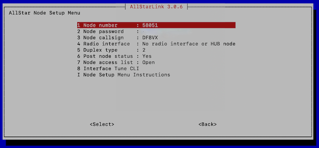
Node Registration: Log into the AllStarLink website, where you can register your node, obtain a node number, and get a password. This will allow your node to connect to the AllStarLink network. You need the information to setup your Node with the asl-menu. Enter your node number and the password for your node from the AllStarLink website. Node callsign shoud be your call sign. Since this is a node without a radio choose HUB node. Full duplex works for me and sharing the node status on AllStarLink website doesn’t hurt. My node is open for connections until some Jokers might find it funny to establish multiple connections and spam the network.
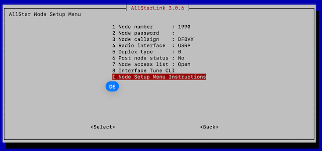
Setting up a private Node: This process is similar to the first node. Except you need to keep the node number below 2000. In my setup I use 1990, use USRP and half duplex.
Add User for DVSwitch mobile
To access the node via DVSwitch mobile edit /etc/asterisk/iax.conf
[df8vx]
type = friend
context = iax-df8vx
auth = md5
secret = YourPasswordHere
host = dynamic
disallow = all
allow = ulaw
allow = adpcm
allow = gsm
transfer = no
and /etc/asterisk/extensions.conf.
[iax-df8vx]
exten => ${NODE},1,Ringing()
        same => n,Wait(10)
        same => n,Answer()
        same => n,Set(CALLSIGN=${CALLERID(name)})
        same => n,NoOp(Caller ID name is ${CALLSIGN})
        same => n,NoOp(Caller ID number is ${CALLERID(number)})
        same => n,GotoIf(${ISNULL(${CALLSIGN})}?hangit)
        same => n,Playback(rpt/connected-to&rpt/node)
        same => n,SayDigits(${NODE})
        same => n,rpt(${NODE}|P|${CALLSIGN}-P)
        same => n(hangit),NoOp(No Caller ID Name)
        same => n,Playback(connection-failed)
        same => n,Wait(1)
        same => n,Hangup
Repeat above for every additional user you want to add.
Step 5: Install Allmon3
Note: Detailed instructions and additional information can be found at the official AllStarLink documentation site.
cd /tmp
wget https://repo.allstarlink.org/public/asl-apt-repos.deb12_all.deb
dpkg -i asl-apt-repos.deb12_all.deb
apt update
apt install allmon3
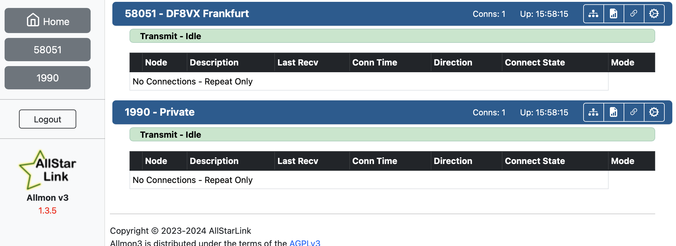
Allmon3 is now available at http://[YOUR_IP]/allmon3.
For my two nodes I extended /etc/allmon3/allmon3.ini by the following:
[58051]
host=127.0.0.1
user=admin
pass=YOUR_PASSWORD_HERE

[1990]
host=127.0.0.1
user=admin
pass=YOUR_PASSWORD_HERE
The password can be set and found in the asl-menu. It should look more or less similar to this.
Step 6: Install DVSwitch
cd /tmp
wget dvswitch.org/bookworm
chmod +x bookworm
./bookworm
apt update
apt install dvswitch-server
apt install php-cgi libapache2-mod-php8.2
To configure DVSwitch for inital setup, simply change directory to /usr/local/dvs and ./dvs to enter the menu.
Changes are made in /opt/Analog_Bridge/Analog_Bridge.ini to bridge ASL to YSF at txPort = 35103, rxPort = 35100 and ambeMode = YSFN. Adjusting usrpAudio is not mandatory. These settings work for me.
[AMBE_AUDIO]
address = 127.0.0.1                     ; IP address of xx_Bridge
txPort = 35103                          ; Transmit TLV frames to partner on this port
rxPort = 35100                          ; Listen for TLV frames from partner on this port
ambeMode = YSFN                          ; DMR, DMR_IPSC, DSTAR, NXDN, P25, YSFN, YSFW (encode PCM to this format)
minTxTimeMS = 2500                      ; Analog -> Digital Minimum time in MS for hang delay (0-10000)

; The metadata below is used when ASL is the source since it does not have any concept of digital modes
gatewayDmrId = 2620365                  ; ID to use when transmitting from Analog_Bridge 7 digit ID
repeaterID = 262036590                  ; ID of source repeater 7 digit ID plus 2 digit SSID
txTg = 9                                ; TG to use for all frames sent from Analog_Bridge -> xx_Bridge
txTs = 2                                ; Slot to use for frames sent from Analog_Bridge -> xx_Bridge
colorCode = 1                           ; Color Code to assign DMR frames

; Information for USRP channel driver.  This interface uses PCM to transfer audio information
; There are two typical configurations, ASL and Transcode.  ASL (AllstarLink) is for analog clients connected
; to a digital network.  Transcode is when Analog_Bridge actually points its PCM interfaces back at itself,
; causing a TLV <-- (pcm <--> pcm) --> TLV type of architecture.
;   When using ASL, this matches the rpt.conf ASL file with a setting like:
;   rxchannel = usrp/127.0.0.1:34001:32001
;   When Transcoding, make two ini files and set txPort equal to the other instance rxPort (crossover).  Launch
;   each instance with its own ini file.
[USRP]
address = 127.0.0.1                     ; IP address of USRP partner (Analog_Reflector, Allstar/Asterisk or another An>
txPort = 32001                          ; Transmit USRP frames on this port
rxPort = 34001                          ; Listen for USRP frames on this port
usrpAudio = AUDIO_USE_GAIN              ; Digital -> Analog (AUDIO_UNITY, AUDIO_USE_GAIN, AUDIO_USE_AGC)
usrpGain = 3.0                          ; Gain factor when usrpAudio = AUDIO_USE_GAIN (0.0 to 5.0) (1.0 = AUDIO_UNITY)
;usrpAGC = -20,10,100                  ; Set the agc threshold (db), slope (db) and decay (ms)
tlvAudio = AUDIO_USE_GAIN               ; Analog -> Digital (AUDIO_UNITY, AUDIO_USE_GAIN, AUDIO_BPF)
tlvGain = 0.35                          ; Gain factor when tlvAudio = AUDIO_USE_GAIN (0.0 to 5.0) (1.0 = AUDIO_UNITY)
In /opt/MMDVM_Bridge/MMDVM_Bridge.ini the GatewayAddress and GatewayPort are set to my YSF Reflector. All other networks are set to enable=0.
[System Fusion]
Enable=1

[System Fusion Network]
Enable=1
LocalAddress=0
LocalPort=3200
GatewayAddress=85.209.49.6
GatewayPort=42003
Debug=0
My persoanl Data is added in /opt/YSFGateway/YSFGateway.ini. Startup=DE-DF8VX is pointing to my Room in the YSF Network.
[Info]
RXFrequency=433737500
TXFrequency=433737500
Power=1
Latitude=50.1389
Longitude=-8.6453
Height=0
Location=Frankfurt, Germany
Description=DVSwitch
URL=https://groups.io/g/DVSwitch

[Network]
Startup=DE-DF8VX
InactivityTimeout=0
Revert=0
Debug=0
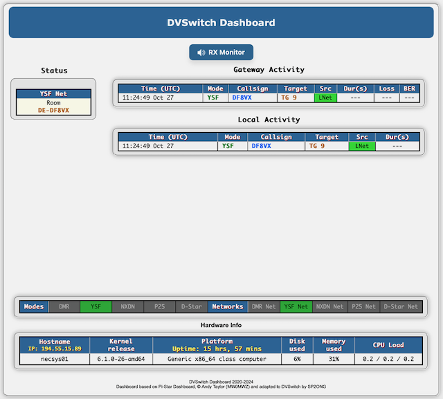
The DVSwitch dashboard is available at http://[YOUR_IP]/index.php. Because my Pi-star is also connected to DE-DF8VX I can press the PTT on my FTM-200 and see Gateway Activity on the dashboard.
Step 7: Connecting Nodes and Testing Communication
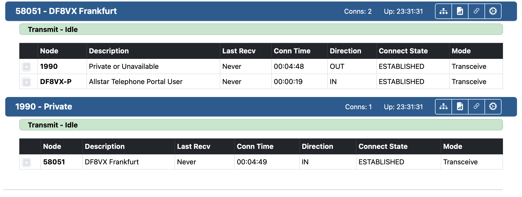
To finalize the setup, we need to establish a link from Node 58051 to Node 1990, which serves as the bridge to the YSF Reflector room DE-DF8VX. This allows seamless communication across nodes using AllStarLink, with Node 58051 as a connection point for DVSwitch Mobile and other connected devices.
Linking Nodes with Allmon3
- Access Allmon3: Start by logging into Allmon3, the AllStarLink management interface.
- Connect Node 58051 to Node 1990: Within Allmon3, locate Node 58051 and select Connect to establish a link to Node 1990. Once connected, any radio transmissions on Node 58051 will also transmit through Node 1990, allowing cross-linking with the YSF Reflector.
You’ll notice the nodes are linked if you press PTT on your radio and see activity between the nodes.
Connecting DVSwitch Mobile for Remote Access
With DVSwitch Mobile on an Android device, you can link directly to Node 58051. Here’s how:
- Connect DVSwitch Mobile: Enter the IP address and port of your AllStarLink server (Node 58051).
- Authenticate: Use the username and password set earlier in
/etc/asterisk/iax.conf.
After connecting, DVSwitch Mobile (e.g., showing as DF8VX-P) becomes part of the AllStarLink network. You can test the entire setup by using the Android device to communicate with the Yaesu FTM-200. You should hear your transmission across both devices, confirming that the nodes are properly linked and operational.
This setup allows flexible communication, enabling you to transmit and receive between different devices, all routed through the YSF Reflector bridge on Node 1990.
Final Step: Expanding Communication Across the Network
With the link established between Node 58051 and Node 1990, you’re now able to connect to any other AllStarLink node and communicate through your Yaesu FTM-200. This setup allows seamless interaction across the AllStarLink network, extending your reach to any linked node and their associated devices.
By crosslinking with nodes connected to other digital modes such as D-Star, DMR, P25, or M17, you open up even more options for versatile, multimode communication. However, this expanded connectivity comes with a key technical consideration: network loops.
Understanding and Avoiding Network Loops
When linking multiple nodes, especially across different digital modes, network loops can easily form if two or more interconnected nodes link back to each other in a circular path. This is particularly risky in networks with crosslinks, where transmissions across one mode can feed back into another, creating a continuous feedback loop.
How Loops Occur
For example, if Node A (AllStarLink) is crosslinked with Node B (YSF) and Node B then links back to Node A or another AllStarLink node that connects indirectly back to Node A, this can create a circular path. When one person transmits, the audio can loop around endlessly, broadcasting back and forth between nodes. Loops lead to:
- Echoing and feedback: Continuous audio repetition disrupts network usability.
- Bandwidth drain: Constant retransmissions clog bandwidth, impacting the performance of all nodes in the loop.
- System strain: Some devices or servers may experience crashes or increased CPU load, depending on loop intensity.
Best Practices to Avoid Loops
-
Link Awareness: Carefully plan your connections to avoid redundant paths. If using allmon3 or other monitoring tools, visualize node links and double-check new connections for potential loop risks.
-
Manual Disconnects: Regularly monitor and manually disconnect any unintended or indirect links that could form loops. A good practice is to review active links before making additional connections to prevent overlapping paths.
-
Single Path Principle: Aim to establish a single, clear path between nodes for each crosslink connection. Avoid connecting two nodes in both directions unless you’re certain it won’t create a feedback path.
-
Loop Prevention Settings: Some nodes and applications provide loop prevention settings, including timeout configurations to break repeating transmissions. Check if your setup supports these features.
-
Testing and Monitoring: Regularly test your network for stability after adding new links, particularly crosslinks to digital modes. Observe your network traffic and audio quality to detect signs of loops early.
By following these guidelines, you can safely expand your network and communicate across multiple nodes and digital modes without the risk of disruptive loops.

